UL Listed10-Year WarrantyDesigned for measurable energy and equipment savings
INSTALLATION

See Exactly How Flowāv Is Installed.

A clear manual-based process covering safety, panel review, grounding, mounting, parallel wiring, commissioning, verification, and troubleshooting.

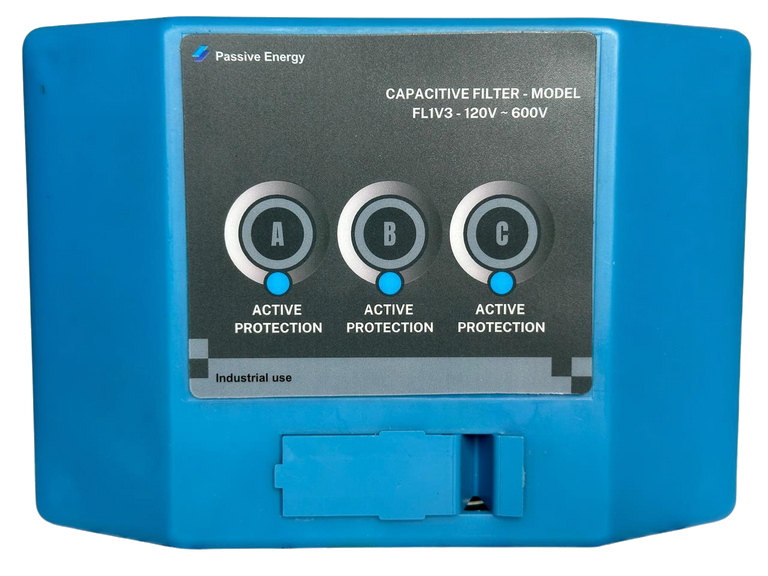
Flowāv FL1V3 product
PURCHASE & INSTALLATION

Product and installation are separate.

Flowāv equipment is purchased from Passive Energy Solutions. Electrical installation is performed and billed separately by a qualified licensed electrician.

Request Installation Guidance →
BEFORE WORK BEGINS

Qualified personnel, correct PPE, and a de-energized system.

Installation and servicing must be performed by licensed electricians or technicians trained in electrical systems and power quality. All work must follow applicable NEC, OSHA, and local code requirements.

1

De-energize and lock out

All power sources must be de-energized before work begins. Apply the site’s lockout/tagout procedure before opening or modifying the panel.

2

Confirm product match

Verify that the Flowāv voltage rating matches the electrical system and that the planned installation meets the project’s phase and sizing requirements.

3

Verify grounding

Ground resistance must be less than 10 ohms, verified with an approved clamp meter or earth tester. A low-impedance ground is essential for safety and optimal performance.

4. INSTALLATION PROCEDURE

Simple enough to follow. Specific enough to install correctly.

4.1

Pre-installation checklist

  • Inspect the panel enclosure for moisture, dirt, or damage.
  • Confirm the product voltage rating matches the system.
  • Verify grounding resistance is below 10 ohms.
  • Confirm the correct Flowāv quantity for the project’s kWh and electrical profile.
  • Confirm suitable mounting space, ventilation, breaker capacity, conduit route, and code requirements.
Core FL1V3 specifications120-600V AC45-65 HzDIN rail or panel mount-4°F to 140°FApprox. 6.5 × 4.5 × 3.3 in.IP55 unit; use the required listed enclosure for the environment
4.2

Mounting

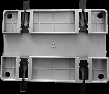
  • Mount the unit on a standard 35 mm DIN rail, or securely fasten it to the panel using the approved mounting method.
  • Install it where airflow is not obstructed and where the unit is protected from direct heat sources.
  • For harsh environments, use an appropriately UL-certified IP65/NEMA 4X enclosure.
  • Make sure the rail or panel support can securely hold the unit.
DIN rail mounting component shown in the Flowāv manualDIN rail / panel mounting component shown in the user manual.
4.3

Parallel wiring

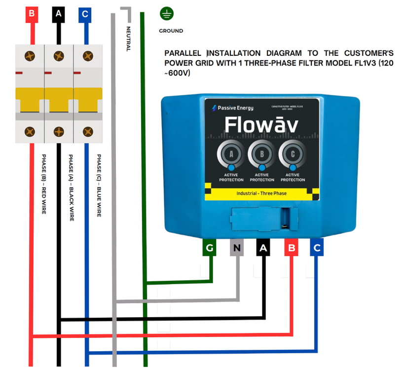
Flowāv is connected in parallel with the customer’s power grid. The existing loads continue to operate through the original electrical system.

  • L1, L2, L3: connect across the applicable phases.
  • Neutral: connect where the project uses the line-to-neutral configuration shown in the approved design.
  • Ground: bond to the facility grounding electrode system in accordance with NEC requirements.
  • Use the specified conductors and one properly rated, UL-listed circuit breaker per unit.
  • Final wiring must follow the approved project diagram, product labeling, and local code.
Flowāv FL1V3 three-phase parallel installation diagramThree-phase parallel installation diagram from the FL1V3 US Standards Manual.
5. SYSTEM COMMISSIONING

Power up, read the indicators, and verify the installation.

A

Initial power-up

After the electrician completes all checks and safely energizes the dedicated breaker, observe the front LED indicators.

All three LEDs on: normal operating indication.
One or more LEDs off: stop and check wiring before proceeding.

B

Electrical verification

Use appropriate test equipment, where available, to verify voltage, grounding, connection, and operating condition. The manual references equipment such as a Fluke 1738 for performance verification.

C

Document and hand over

Record the model, serial number, panel, voltage, phase, breaker, grounding result, installer, date, LED status, baseline readings, and warranty information.

Need the installation reviewed before work starts?

Send the panel details, system voltage, phase, recent utility usage, and available one-line diagram.

Request Installation Review →
6. TROUBLESHOOTING GUIDE

Start with the simplest checks.

Only qualified personnel should open a panel, test energized equipment, or correct electrical wiring.

SymptomLikely causeCorrective action
No LED / no operationNo power inputCheck the dedicated breaker and wiring.
No performance detectedPoor grounding or incorrect installationCheck grounding and verify the correct parallel wiring configuration.
OverheatingPoor airflow or overloadEnsure proper ventilation and verify the panel load and installation environment.
High THDIncorrect parameters or project sizingConfirm that the number and configuration of Flowāv units follow the project’s kWh and design guidelines.

Flowāv is a passive, parallel-installed power-quality filter. It is not an active voltage-monitoring relay.

INSTALLATION FAQ

Practical answers before scheduling the work.

Does Flowāv replace the electrical panel?

No. It is added in parallel to the existing system according to the approved installation design.

Can the unit be mounted inside any environment?

The location must meet the product’s temperature, ventilation, ingress-protection, enclosure, and code requirements. Harsh environments may require an IP65/NEMA 4X listed enclosure.

Does the building need to be shut down?

Electrical work must be de-energized and performed under proper lockout/tagout procedures. The scope and duration of any shutdown depend on the panel, site safety rules, and the electrician’s plan.

What should be checked if savings are not visible?

Verify power to the unit, LED status, grounding below 10 ohms, correct parallel wiring, correct project sizing, operating conditions, and the measurement period used to compare performance.

What information is needed to size the project?

Recent utility usage, voltage, phase, panel information, major loads, operating hours, and any available power-quality or one-line-diagram data.

Where can an installer see the full technical requirements?

Use the official FL1V3 US Standards Manual and the project-specific electrical design. Download the manual →

Get My Free Energy Audit →